What is CC1101?
The CC1101 module is a low-cost sub-1 GHz transceiver designed for very low-power wireless applications.
The RF transceiver includes a highly configurable baseband modem. The modem supports various modulation formats and has a data rate configurable up to 600 kbps. The CC1101 has extensive hardware support for packet processing, data buffering, burst transmissions, clear channel assessment, link quality indication, and wake-on-radio.
An SPI interface can be used to control the CC1101's main operating parameters as well as its 64-byte transmit/receive FIFOs. The CC1101 is typically used in conjunction with a microcontroller and a few other passive components in a typical system.
CC1101 Pinout
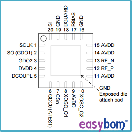
(for detailed pin configuration info, please look up in the datasheet)
CC1101 Key Features
- RF Features
High sensitivity
Low current consumption
Adjustable frequency bands range: 300-348 MHz, 387-464 MHz, and 779-928 MHz
Programmable data rate: 0.6-600 kbps
Programmable output power: up to +12 dBm for all usable frequencies
Prominent receiver selectivity and blocking performance
- Analog Features
Supports for 2-FSK, 4-FSK, GFSK, MSK, OOK, flexible ASK shaping
Integrated analog heat sensor
Automatic frequency compensation (AFC)
Fast settling frequency synthesizer: 75 μs settling time
- Digital Features
On-chip support for sync word detection
High-performance SPI interface
Digital RSSI (Received Signal Strength Indicator) output
Programmable CS (Carrier Censor) indicator and channel filter width
Programmable Preamble Quality Indicator (PQI) for enhanced protection against false sync word detection in random noise
Automatic Clear Channel Assessment (CCA) before transmitting
- Low Power Features
Where to Use CC1101 Module

(CC1101 module block diagram)
Typical application areas of CC1101 transceiver:
Wireless sensor networks
Wireless MBUS
Industrial monitoring and control
AMR – Automatic Meter Reading
Ultra-low-power wireless applications operating in the 315/433/868/915 MHz ISM/SRD bands
Home and building automation
Wireless alarm and security systems
Frequency hopping systems
Use CC1109 to Increase CC1101 Range
In some cases, extending the CC1101 range may be necessary. Texas Instruments' CC1190 is a range extender for 850-950 MHz RF transceivers, transmitters, and System-on-Chip devices.

(CC1101 + CC1109 range-increasing circuit)
It expands the link budget by including a power amplifier (PA) for increased output power and a low-noise amplifier (LNA) with a low noise figure for improved receiver sensitivity, as well as switches and RF matching for easy design of high-performance wireless systems. The performance figures for the CC1101 + CC1190 combination can be found in AN094 and AN096. The simplified circuit is shown above.
CC1101 Arduino Example - RF Receiver and Transmitter
Important Technical Parameters of the CC1101
CRC error detection and built-in hardware address multipoint communication control
Buffer size: Separate 64-byte RX and TX data FIFO
Transmission distance: 300 – 500 meters (Depending on the specific situation of the environment and communication baud rate, etc.)
Header Pin Pitch: 2.0mm
Maximum operating speed: 500kbps, support 2-FSK, GFSK, and MSK modulation
Programmable control of output power, the maximum output power of +10dBm
Current consumption: (RX, 15.6mA; 2.4kbps, 433MHz)
Sensitivity: (<1.2kbps -110dDm, 0.1% packet error rate)
Input voltage:3.3V
Materials You'll Need
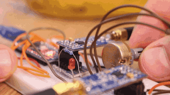
Arduino RF Transmitter and Receiver Connection Schematic

(image credit: https://electronoobs.com/eng_arduino_tut98.php)
This is a CC1101 radio module with an Arduino NANO board communicating in SPI serial. The module range could be 400m at maximum.
The schematic is straightforward, but there are a lot of pins. We have two Arduino NANOs, and in this case, we will use 3.3V from the Arduino. If this fails, connect an external 3.3V power supply and share ground. Connect the SPI pins, and then add a potentiometer, an LED, and a resistor. Upload the following codes to the transmitter and receiver, and read the comments in the code for more information. If it works, you can use the radio connection to adjust the brightness of the LED.
(image credit: https://electronoobs.com/eng_arduino_tut98.php)
You can find codes, connecting demonstrating video and the CC1101 library on the URL above.
Other CC1101 Arduino Examples such as an RF sniffer, an RC-switching remote control that might catch your attention:
https://www.grspy.com/cloning-the-remote-control-of-an-rc-switch-using-ti-cc1101/
https://create.arduino.cc/projecthub/kls/arduino-knx-rf-packet-sniffer-7b7a58
https://z4ziggy.wordpress.com/2014/06/27/rf-sniffer-open-gates-cars-and-rf-remote-controlled-devices-with-ease/
Download CC1101 Datasheets
For more information about CC1101 application notes, frequency programming, radio control, data rate programming, pin configuration, etc. please go to the TI website and search by the part code.
 Marshall ·


