You'll learn

What is a Ferrite Bead?
Did you ever wonder what this tiny "choke" at the end of your laptop or cellphone charger is?
Well, that's a typical ferrite bead to attenuate high-frequency currents and suppress excessive EMI (electromagnetic interference) on a cable that can cause interference to other electric appliances. Thus, it is also called an EMI ring/EMI filter. Sounds fancy but a ferrite bead is one of the simplest interference filters that cost little and achieves effective filtering outcomes.
Operating Principles of a Ferrite Bead

The operating principle of this type of filter with high reactance is that when the high-frequency alternating currents try to cross the part of the cable where the "shock" or ferrite core is located, the self-inductance produced by the magnetic flux of the current that tries to pass through it generates a back EMF that opposes the passage of its alternating component according to Faraday's Law.
However, this filter does NOT prevent direct current (DC), or low-frequency alternating current from passing through it and continuing to flow freely throughout the cable and the rest of the electronic circuit.
Ferrite Bead Symbol
On PCB design, ferrite beads have a number of schematic symbols. The symbol has not been standardized in the same way that other components have. Many people treat them as if they were simple inductors, while others treat them as if they were a resistor, and some even give them a special symbol. If you search through Google, you may get ferrite bead symbols as shown in the diagram above.

For instance, the below is a ferrite bead with 270 Ohm (Ω).

Types of Ferrite Beads
The term “ferrite beads” can be referred to 2 different types of its kind: wirewound ferrite bead and SMD ferrite bead (which is the traditional chip type).

Ferrite beads SMD offer limited options for both attenuation and frequency range, whereas wirewound ferrite beads provide a high magnitude of attenuation over a large frequency range (from 100 MHz and above). In addition, wirewound ferrite beads offer reduced DC resistance (DCR) and greater current ratings.
(source: https://article.murata.com/en-sg/article/basics-of-noise-countermeasures-lesson-4)
Figures 1 and 2 show how wirewound ferrite beads outperform both low- and high-DCR chip ferrite beads in terms of broadband performance. Figure 1 compares the Coilcraft 0402DF-121 wirewound ferrite bead to the 0402-sized chip ferrite bead with the lowest DCR. The 0402DF has a higher impedance across the frequency range, allowing for more filtering at frequencies above 100 MHz. When compared to standard high-DCR chip ferrite beads, the Coilcraft wirewound ferrite bead maintains the same high-frequency attenuation while offering higher current ratings and 40% better DCR.
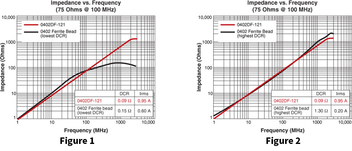
(source: https://www.coilcraft.com/)
Ferrite Bead vs. Inductor
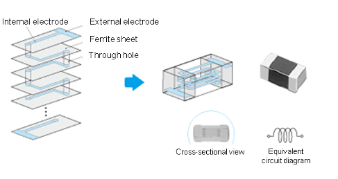
To put it simply, a ferrite bead is a special kind of "lossy" inductor. As for the structure, all SMD ferrite sleeves are comprised of the inner coil as inductors, but in a multiple layers way. However, there are still obvious differences between the two, which account for filter characteristics.
Specifications
Although the ferrite bead is an inductor, its specification will be different from that of the available inductor because it considers the impedance characteristics of a specific frequency band. Ferrite will take the impedance at a specific frequency (unit ohms) as its specification.
For example, 22R@100MHz means that the impedance of the magnetic beads in the 100MHz frequency band is 22 ohms. Generally, the impedance characteristics of magnetic beads in different frequency bands will be listed in the specification.
Low Q Factor and High Resistance Component R-Value
(source: https://techweb.rohm.com/)
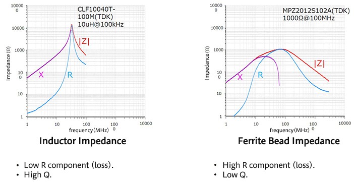
Ferrite beads are generally designed as inductor components with a low Q factor. The heat generated will heat the ferrite, but the heat generated is generally negligible. This means ferrite cores outperform inductors in reducing noise over a broad range of frequencies.
Loss does not accompany the reactance component, but it accompanies the resistance component R. This means that, compared to normal inductors, chip ferrite beads absorb more noise energy, offering a greater noise-suppression effect.
DC Characteristics Performance
(source: https://techweb.rohm.com/)
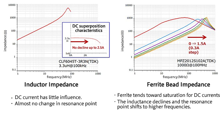
Inductors can sustain relatively larger DC superposition currents, and the DC has little effect on the impedance within this range, with essentially no change in the resonance point.
On the other hand, ferrite cores readily attain saturation, which causes the inductance to decline and the resonance point to shift to higher frequencies. As a result, the ferrite bead appears more like a resistor.
Ferrite Bead Typical Use and Schematics Examples
A ferrite bead inductance calculator is used when working with ferrite bead inductor components to determine the values required to suppress EMIs present in your design's electronic components.
Ferrite Bead for Headphones
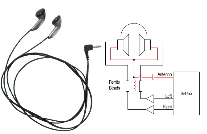
A standard headphone cable has three conductors. A headphone amplifier drives the left and right audio channels onto the left and right audio conductors, while the common audio conductor serves as the audio return path. The same cable also serves as the FM antenna, with an inductor blocking RF from the ground while allowing the audio signal to return to the ground.
A small blocking capacitor allows antenna RF to pass to the receiver front end but prevents receiving audio from that antenna input. The ferrite beads provide a low-impedance audio path and a high-impedance RF path between the headphone amplifier and the headphone.
T/Pi Filters

The most common way to use a ferrite as a filter is to connect it to a small resistor in series or connect it to capacitors in a T or Pi filter circuit. The above diagram, which consists of two capacitors and a ferrite, can suppress high-frequency noise on a power line and separate noisy and sensitive circuits.
Ferrite LC Filters

LC filters are another ferrite bead purpose used to prevent noise from propagating from one circuit section to another. A ferrite bead is an excellent choice because it acts as an inductor at low frequencies and as a resistor at high frequencies, where the regulator is likely to oscillate. Between capacitors, a ferrite bead or choke can help reduce white noise from the regulator and switching noise coupled from the source. In the latter case, it is preferable to place the filter in front of the regulator, and in the former case, it is preferable to use a regulator with a reference filter pin.
Ferrite Bead Selection Guidelines and Cautions
As mentioned before, ferrite cores tend to be saturated as DC currents increase, denoting a narrow filtering band of frequencies that a ferrite choke can deal with. So it is always important to choose ferrite beads whose resistive band contains the unwanted frequencies estimated.
Plus it'll be helpful if the manufacturer offers impedance derating curve diagrams corresponding with DC, temperature, or frequency which vividly demonstrate the DC resistance spec of the part and should be taken into consideration in your design.

(source: Murata BLM series SMD Ferrite Beads datasheet)
While in practice, choosing which ferrite beads to go is usually decided on former experience and may also take account of statistics from the EMC lab results. Moreover, there are situations where ferrite beads are not recommended. Here are two main misuses of ferrite beads in high-speed/high-frequency circuits.
Dealing with DC Bus Ripple Voltage
In modern electric appliances, especially in high-speed digital components, ferrite beads as a low-pass filter might experience a power integrity problem called the PDN impedance. All PCB designs don't want to have. PDN impedance could add to the transient voltage disruption, which gets seen in all other ports of the power bus. This, in reality, makes ferrite choke itself a source of EMI.
Bridging Split Ground Planes
(source: https://www.nwengineeringllc.com/article/are-ferrite-beads-needed-in-todays-electronics.php)
Another common mistake in using ferrite cores is to tie split ground planes. First and foremost, you must not split the ground planes in mixed-signal designs since it brings problematic routing and multiple EMI. You can't get a low impedance return path by connecting two separate ground planes with ferrite beads when return signals are laid with high-frequency components. In contrast, the ferrites alone can create lumped LC resonance and degrade the grounding system.
Author's Thoughts
Meanwhile, remember ferrite bead is not the only solution to suppress EMI noises (alternatives include bypass capacitors, shunt capacitors, and more). Furthermore, ferrite products take many forms that provide similar EMI shielding purposes including ferrite plates, elastomers, shielding cans, etc. You should try to avoid using these extra shielding materials because they will increase the system's cost and weight.
Read On
>> How to Understand EMI Filters?
 Marshall ·


