Rotary encoders are usually used in devices such as proximity switches and photoelectric switches. Their function is to control the speed and movement direction of the conveyor belt. It has high reliability, high environmental adaptability, and excellent controllability. The correct wiring method is very important to the normal operation of the machine. This article will divide into the following contents: what does a rotary encoder do? what is the rotary encoder working principle, and what is its wiring method? First, let's understand what it is and how it works.

What does a Rotary Encoder Do?
It is a type of sensor. It can be used to detect position and speed. It is detected by converting rotating mechanical displacement into electrical signals and processing these signals.
How is Rotary Encoder Working?
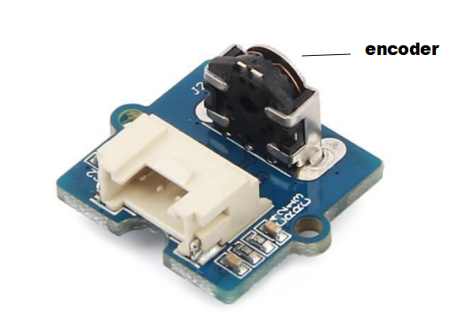
Let's look closer at the encoder to understand the way it works. It is an elongated disk that has equally spaced contact zones. It can be connected with the same pin as well as two separate pins for contact, A and B as illustrated in the following.

If the disk starts turning step by step the pins A and B begin to make contact with one another, the two output signals of a square wave will be generated in accordance with the situation. Both outputs could be used for the determination of the rotational position when we simply count the signals' pulses. If we wish to determine the direction of the rotation also, we have been able to analyze both signals simultaneously. We can see that both output signals are separated by 90 degrees from one another. If the encoder is turning clockwise, output A is in front of output B.
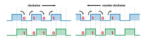
We should take a look at the steps every time the signal changes from Low to High or from High to Low. We can see at the time, the output signals are of opposite values. In the reverse case, if it is moving counterclockwise, the output signals are counter-clockwise.
Rotary Encoder Arduino
We could come up with a practical illustration of this by using the Arduino. The specific module I'm using for this demonstration is the breakout board, which includes five pins. The first pin represents the output The next pin represents the B output, and the third pin acts as the Button pin. The two other pins correspond to the VCC as well as the GND pin.

Encoder Wiring Method
The rotary encoder wiring diagram may be unique and should follow the chart or pin arrangement specified. The wiring of a multi-channel with commutation tracks can have up to 14 wires. Wiring errors can cause signal problems, such as pulse distortion, low signal amplitude, and connection short circuits. Below is the Rotary encoder wiring diagram.

Rotary encoder wiring diagram
Reduce Signal Noise
An optical encoder cannot be used as a feedback device without wiring. The wire serves as a route for receiving radiation signals. The length of the cable affects the effect. In an environment with high electromagnetic interference, the application of technology should be considered first to prevent noise. The wiring should be laid in conduit, preferably separated from other wires. If this is not possible, they should only run with other low-power DC cables. The signal wire should be at least 1 foot away from the power wire.
Rotary encoder keyboard
Shielding is significant. We should use a foil sheath with a drain wire or a grounded braided wire shield to protect the cable. For very sensitive applications or high electromagnetic interference environments, metal foil sheathed wire and overall braided wire shielding around the cable should be used.
Grounding Encoder Wire
Neither the encoder housing nor the cable/connector should be grounded. We can only ground one end of the cable. Multi-point grounding will generate ground loops, which can lead to AC-induced noise. The best way is to ground it through the connector, preferably on the driver's side, assuming the driver is grounded.
In an industrial environment, motors, remote switches, and magnetic fields generate high current fluxes. When the potential of different grounding points changes, we can ground the cable shield and all other parts of the system that need to be grounded from a point on the instrument end.
Prevent Motor Shaft Current
The variable frequency drive induces a current in the shaft, rotor, and housing of the motor. This is because the switching frequency is high. Electric current passes through the bearing, which will damage the balls in the raceway.
We need to galvanically isolate the encoder from the shaft. This can be done using a grounding brush that directly contacts the motor shaft. The shaft is in turn connected to the motor frame so that any induced current will flow directly to the motor frame. This can protect it and motor bearings.
Encoder Phase and Reverse Phase
The quadrature encoder can measure position through two pulse signals. This signal can be called signal A (channel A) and signal B (channel B). The offset between signal A and signal B is 90°, which is used to determine the direction in which it moves. If signal A is before signal B, it rotates in a clockwise direction. On the contrary, it rotates counterclockwise.
 Anita ·


