


KD-KA01
Cecelia is an accomplished electrical engineer with expertise in automation and control systems. She is a natural problem-solver and thrives on developing solutions that optimize performance and efficiency.
Isolation transformer refers to the transformer with electrical isolation between the input winding and the output winding. The isolation transformer is used to avoid accidental contact with the live body at the same time. The isolation of the transformer is to isolate the respective currents of the primary and secondary windings. In the early days, it was used in the power industry in European countries and was widely used in the control power supply of general circuits, security lighting, and indicator lights in the electronics industry or industrial and mining enterprises, machine tools, and mechanical equipment.
There is a special transformer with high insulation strength between the primary side and secondary side windings to isolate different potentials and suppress common-mode interference. The transformation ratio of the isolation transformer is usually 1:1.
isolation transformer purpose is to completely insulate the electricity between the primary side and the secondary side and to isolate the circuit. In addition, the high-frequency loss of its iron core is used to suppress the introduction of high-frequency clutter into the control loop. Using an isolation transformer to suspend the secondary to the ground can only be used in situations where the power supply range is small and the line is short. At this time, the capacitance current of the system to the ground is too small to cause personal injury. Another very important role is to protect personal safety! Isolate hazardous voltages.
With the continuous development of the power system, the transformer plays an increasingly important role as a key device in the power system, and its safe operation is directly related to the reliability of the entire power system. The deformation of the transformer coil refers to the axial and amplitude dimensional changes, body displacement, coil twist, etc. after the coil is subjected to force.
There are two main reasons for the deformation of the transformer coil: one is that the transformer is inevitably affected by external short-circuit faults during operation; the other is the accidental collision of the transformer during transportation and hoisting.
Isolation transformers provide electrical isolation between AC power lines (mains) and powered equipment. This means that there is no DC path between the two windings. They are mainly used for three purposes:
1. Isolate the secondary winding from ground
2. Provide the rise and fall operation of the line (mains) voltage
3. Reduce the transmission of line noise from the primary winding to the secondary winding and vice versa
Isolation transformers share common characteristics of transformers (Figure 1). Primary and secondary windings are wound on a common ferromagnetic core.

Figure 1: Schematic of a simple power transformer consisting of an NP-turn primary winding and an NS-turn secondary winding on a common ferromagnetic core.
In the figure, the primary winding has NP turns around the ferromagnetic core and the secondary winding has NS turns. The relationship between the primary voltage (VP) and the secondary voltage (VS) is shown in Equation 1:
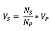
If the primary winding has more turns than the secondary winding, the voltage on the secondary winding will be lower than the voltage on the primary winding. This is a buck configuration. If the primary winding has fewer turns than the secondary winding, the voltage on the secondary winding will be higher than the voltage on the primary winding, resulting in a boost configuration. Most isolation transformers have the same number of turns in the primary and secondary windings, therefore primary and secondary voltages are the same.
Energy in a transformer is conserved, so if we ignore losses, the product of VP and the primary current (IP) will be equal to the product of VS and the secondary current (IS). The power rating of a transformer is determined by multiplying the RMS voltage of the primary winding by the RMS primary current. This is "apparent power," measured in volt-amperes or VA.
The points on the schematic are phasing points that indicate the primary and secondary current directions. As shown, the current flowing into the primary side of the winding causes a secondary current to flow out of the secondary side of the winding. This is important if the windings are to be placed in series or parallel. Failure to follow the phasing of the windings can lead to errors.
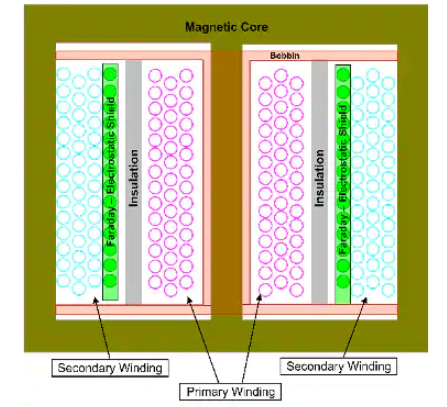
Figure 2: Cross-sectional view of an isolation transformer in shell construction, where the primary and secondary windings are concentrically wrapped around insulating layers with a Faraday shield inserted between the two layers.
A Faraday shield is an electrostatic shield that reduces the capacitance between the primary and secondary windings and is usually grounded. This shielding reduces the magnitude of common-mode noise and transients passing through the transformer.
The primary and secondary windings in an isolation transformer are highly insulated to minimize direct conductance between them. The measure of insulation effectiveness is leakage current. Most isolation transformers are also tested using a high potential or withstand voltage tester. When checking for leakage current, these instruments apply a high voltage across the insulation.
The physical construction of an isolation transformer can take many forms, including shell construction (Figure 2). Among them, the primary and secondary windings wrap the insulating layers in a concentric manner, and the Faraday shield is inserted between the two layers.
Faraday shields can be foil layers or close-wound windings as shown. The ground is usually on the primary side and is connected to the ground. Since the primary and secondary windings already use enameled wire, this construction is called "double insulation".
Alternatively, the windings can be placed side-by-side on the core, which is called a "multi-slot bobbin" configuration, or wound on a toroidal core.
Isolation transformers are available in open construction or enclosed in shielded construction (Figure 3). Hammond Manufacturing's 171E isolation transformer uses a shielded case construction. The end cap shield contains the transformer's magnetic field and is also used to minimize interference from magnetic fields outside the transformer. This 500 VA 1:1 transformer also includes lead, NEMA, three-wire ground input and output connectors, and an integrated overload circuit breaker.
Although the ground wire is connected to the secondary output connector, it is not used in most isolation transformer applications. The leakage current between the primary and secondary of this transformer is less than 60µA at the rated input voltage.
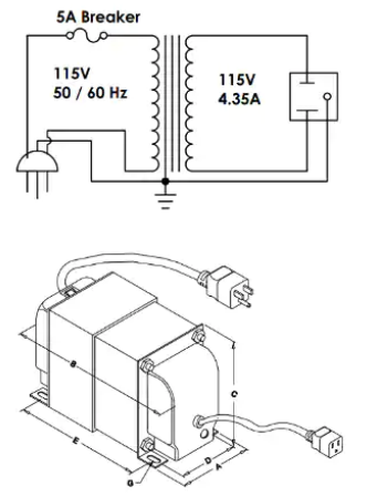
Figure 3: Example of an isolation transformer with a shield on the end cap
The DU1/4 from Bel/Signal Transformer is a 250 VA isolation transformer with open construction with two sets of multi-tap windings. There are two primary and two secondary windings each (Figure 4).
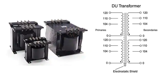
Figure 4: Bel/Signal Transformer's DU1/4 is an open isolation transformer with two sets of primary and secondary tapped windings.
The primary and secondary windings have the same voltage ratings, 0, 104, 110, and 120 volts, respectively. This allows series or parallel connections on the primary or secondary windings. Therefore, for a 110 or 220-volt input, the nominal 1:1 ratio can be maintained. Also, it is possible to configure a step-up transformer from 110 volts to 220 volts, or a step-down transformer from 220 volts to 110 volts. Additionally, multi-tap windings allow intermediate voltage ratings such as 208 volts, 214 volts, or 230 volts (Figure 5).
The power connection of the transformer is screw terminals.
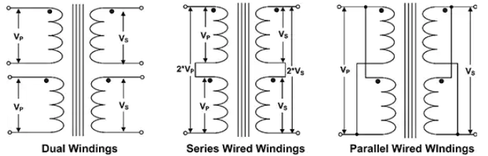
Figure 5: The dual winding of the DU1/4 allows for many possible wiring configurations, including 1:1, 2:1, 1:2 voltage ratios.
If both primary and secondary windings are in series, the transformer is a 220-volt input with a 1:1 voltage ratio. If both the primary and secondary windings are in parallel, it is a 110-volt input, a 1:1 voltage ratio, and the available current is twice that of a single winding. If the primary windings are placed in series and the secondary windings are in parallel, the primary voltage will drop by a factor of two. A 2:1 boost can be achieved if the secondary windings are in series and the primary windings are in parallel.
Isolation transformers used in medical applications must meet stricter leakage current requirements. There are maximum leakage current specifications for ground leakage, enclosure leakage, and patient leakage. Ground leakage refers to the leakage current in the ground wire of the equipment. Enclosure current describes the current flowing from exposed conductive surfaces to the ground through conductors other than the ground wire. Patient leakage is the current flowing through the patient to the ground when normally connected to the device. Most devices in this category are certified to UL/IEC 60601-1.
Triad Magnetics' Model MD-500-U is a 500 VA isolation transformer for medical applications (Figure 6). The transformer is certified to the UL 60601-2 specification by Underwriters Laboratories (UL) with a typical leakage current of 10 µA and a maximum leakage current of less than 50 µA.
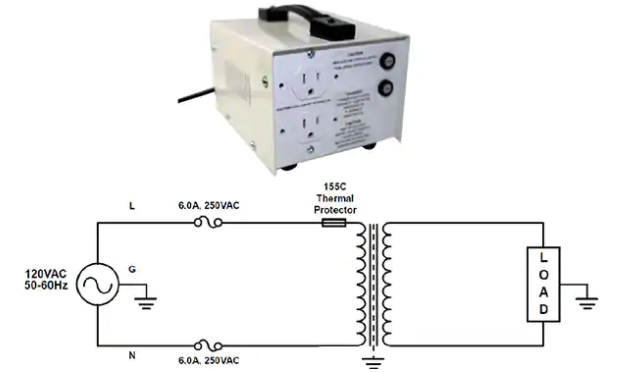
Figure 6: The Model MD-500-U is a 500 VA isolation transformer for medical applications with a leakage current of 10 µA (typ) and uses a toroidal transformer to keep it compact and minimize stray magnetic fields.
The MD-500-U utilizes a toroidal transformer to minimize stray magnetic fields and maximize efficiency while minimizing size. Like most stand-alone medical transformers, it is securely enclosed in a steel case with built-in fuses and thermal cutoff switches.
The focuses of the two works are different. Changing the voltage on-demand and outputting it is the main goal of a normal transformer. Normal transformers can be simply divided into step-down transformers and step-up transformers according to their functional goals. Isolating voltage is not the main task of normal transformers. Some transformers have no isolation between the voltage of the primary side and the secondary side. Normal transformers focus on changing the voltage and cannot isolate the voltage.
The isolation transformer is the special equipment for special purposes. The difference from ordinary transformers is not only that the secondary is not grounded, but there is an isolation layer between the secondary wire packages at the cut place. The isolation layer is only connected to the ground terminal of the primary. Thus the secondary can not only be completely isolated from the electric grid but also isolate from electrostatic fields.
Isolation transformers also have something in common with normal transformers, and their working principles are based on the principle of electromagnetic induction.
The control transformer is used as the power supply of the electrical control circuit to meet the voltage requirements of different electrical components.
Isolation transformer
a. Different voltages at both ends of the transformer or the required voltage signals to be transmitted through the isolation transformer, so that the different voltages at both ends of the transformer will not interfere or affect each other, such as some thyristors or IGBT circuits.
b. It is used for applications that require different impedance matching, such as some audio power amplifiers.
c. It is used for personal safety in some applications, such as the lamp transformer.
The control transformer provides power for the control system during the operation of the electrical equipment;
The isolation transformer is to prevent the electrical equipment from being interfered with by the harmonics of the power supply. In fact, it is a filter with poor performance. Generally, the output voltage of the control transformer is 6.3V, 12V, 24V, 36V, 50V, 110V, 127V, etc. In order to reduce costs, some control transformers only output a single low voltage or three to five voltages. The isolation transformer generally has a transformation ratio of 1:1, and the two types of transformers have different functions, so they cannot be used universally.
For example, in an imported driving electrical circuit, all electrical relays, contactors, etc. are 220 volts, and the power input is 3-phase 4-wire. The control circuit can be formed directly by using the zero line. But this driving car has a control handle, and the electrical designer used an isolation transformer, and the secondary is used as the power supply of the electrical control circuit. Since this secondary circuit has no ground terminal, even if a person touches one of the 220 volts of control voltage, there is no electric shock will occur, so this transformer is both a control transformer and an isolation transformer.
An isolation transformer usually refers to a 1:1 transformer. Its secondary coil is not connected to the ground, and there is no potential difference between any line of the secondary coil and the ground, so it is safe to use.
Isolation transformers are also divided into single-phase isolation transformers and three-phase isolation transformers. Although they have similar functions, they are indeed different types of transformer products. What are the differences between them?
Single-phase isolation transformers are different from three-phase isolation transformers in terms of input and output switching power supply types. The input and output of the single-phase isolation transformer are all signal-phase AC power, which can produce a single-phase power supply. The input and output of the three-phase isolation transformer are all three-phase symmetrical AC currents, which can produce two different types of switching power supplies: three-phase power supply and single-phase switching power supply.
The single-phase isolation transformer is simple in structure and light in weight, so it is more suitable for use in the distribution room network with a relatively small load density. The structure of the three-phase isolation transformer is very complicated, so it is used in various industrial production automation machinery such as packaging and printing, petrochemical equipment, post and telecommunications, and other places where normal working voltage must be ensured.
In general, the difference between single-phase isolation transformers and three-phase isolation transformers is mainly reflected in the types and main uses of I/O switching power supplies. As can be seen from the detailed introduction, both single-phase isolation transformers and three-phase isolation transformers have their own characteristics and advantages.

Cecelia is an accomplished electrical engineer with expertise in automation and control systems. She is a natural problem-solver and thrives on developing solutions that optimize performance and efficiency.

Cecelia · April 26,2022
Transformers are classified by their function, i.e. step-up or step-down. A step-up transformer increases the voltage of the input current, while a step-down transformer reduces the voltage of the input current. The input voltage is called the primary voltage and the output flow is called the secondary voltage.
Basic Electronics Technology/TutorialsAccess:5532

Cecelia · April 21,2022
A step-up transformer is a type of transformer, which has the function of voltage compensation and boosting, and it is also called a step-up compensator.
Basic Electronics Technology/TutorialsAccess:5719

Cecelia · April 20,2022
A power transformer is a static electrical device that is used to convert a certain value of AC voltage (current) into another or several different values of voltage (current) with the same frequency.
Basic Electronics Technology/TutorialsAccess:3509

Cecelia · March 31,2022
Audio transformers are low-frequency transformers and are mainly used for constant-voltage power amplifiers for long-distance broadcast transmissions that do not require high sound quality.
Basic Electronics Technology/TutorialsAccess:5577
Popular Posts
Hot Labels
Popular Parts