


KD-KA01
Cecelia is an accomplished electrical engineer with expertise in automation and control systems. She is a natural problem-solver and thrives on developing solutions that optimize performance and efficiency.

A mass air flow sensor, also known as a mass air flow meter, is one of the important sensors of an EFI engine. It converts the intake air flow into an electrical signal and sends it to the electronic control unit (ECU).
The mass air flow sensor installation location is as follows:
(1) Between the air filter and the throttle body.
(2) On the air cleaner.
(3) On the engine.
There are many types of mass air flow sensors for electronically controlled gasoline injection systems. Common air flow sensors can be divided into vane (wing plate) type, hot film type, hot wire type, and Karman vortex type according to their structural forms.
The structure of the vane-type mass air flow sensor
The vane-type mass air flow sensor is installed on the gasoline engine and is installed between the air filter and the throttle valve. The sensor is composed of an air flow sensor and a potentiometer.
The structure of the vane-type mass air flow sensor
The vane-type mass air flow sensor is installed on the gasoline engine and is installed between the air filter and the throttle valve. The sensor is composed of an air flow sensor and a potentiometer.

1-potentiometer 2-wire plug 3-buffer chamber 4-buffer vane 5-CO adjusting screw 6-bypass channel 7-measuring vane 8-intake air temperature sensor 9-return spring
vane-type mass air flow sensor working principle
The air sucked in by the air filter rushes to the vanes, and the vanes turn to the position where the intake air volume and the return spring balance and stop, that is to say, the opening of the vanes is proportional to the intake air volume. The rotating shaft of the blade is also equipped with a potentiometer, the sliding arm of the potentiometer rotates synchronously with the valve, the deflection angle of the blade increases, the output resistance decreases, and the voltage decreases; if the intake air volume is small, this process is completely opposite.
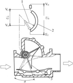
1- the sliding arm of the potentiometer 2- Potentiometer coating resistor 3- Measuring vane
Thermal air flow sensors structure
The main component of the thermal mass air flow sensor is the hot wire resistance, which can be divided into two types: hot wire type and hot film type.
The hot wire of the hot wire heating element is made of platinum wire with a diameter of 70um, which is installed inside the pipe, and is designed to be 120 degrees higher than the intake air temperature.
The hot-film type uses a flat thin-film resistor as a heating element.

Hotwire mass air flow sensor structure
1-Protective net 2-Sampling tube 3-Platinum wire 4-Temperature compensation resistor 5-Control circuit board
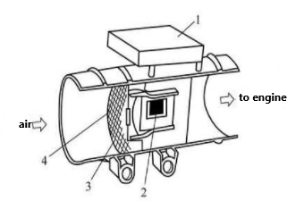
Hot film air flow sensor structure
1- Control circuit 2- Thermal film 3- Temperature sensor 4- Protection net
Thermal air flow sensors working principle
Both the hot wire resistor RH and the temperature compensation resistor RK are placed in the air intake pipe in the air channel, and together with RA and RB, they form a bridge circuit.
The resistance values of RH and RK vary with temperature. When the air flows through the RH, the temperature of the hot wire changes, the resistance decreases or increases, and the bridge is unbalanced. To maintain the balance of the bridge, the current flowing through the hot wire resistance must be changed to restore its temperature and resistance value, the voltage across the precision resistor RA will also change accordingly, and the voltage signal is sent to the ECU as the voltage signal output by the thermal air flow sensor.
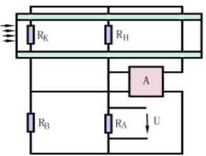
Thermal air flow sensor working principle
1- A: Integrated circuit 2-RH: Hotwire resistor 3-RK: Temperature compensation resistor 4-RA: Precision resistor 5-RB: Bridge resistor
Karman vortex mass air flow sensor structure
The Karman vortex mass air flow sensor is mainly composed of a Karman vortex generator set in the center of the air passage and the corresponding vortex detection devices.

Karman vortex mass air flow sensor structure
1- Reflector 2- Light-emitting diode 3- Metal foil spring 4- phototransistor 5- conducting pressure hole 6- Vortex generator
Karman vortex mass air flow sensor working principle
1-Intake port 2-Pipeline 3-Phototransistor 4-Metal foil leaf spring 5-Pressure guide hole 6-Vortex generator 7-Rectifier grid
A faulty mass air flow sensor can lead to unstable engine idle speed and poor acceleration. This part describes how to detect air flow sensors.
1) When the engine is running, unplug the air flow sensor. If the fault disappears, it means that the air flow sensor signal is deviated and not damaged. The electronic control unit has been performing fuel injection control according to the deviated error signal.
Due to the imbalance of the mixing ratio, the combustion of the engine is not normal, and the engine speed will be unstable or the power will be poor. When the plug of the air flow sensor is unplugged, the electronic control unit will immediately enter the fail-safe function if it cannot detect the intake signal, and replace the air flow sensor signal with the signal of the throttle position sensor, so that the engine continues to work with the substitute value. When the plug of the air flow sensor is unplugged, the fault disappears, which means that the signal is incorrect before the plug is pulled, and the signal is correct after the plug is pulled, so the fault disappears.
2) Measure the dynamic signal voltage at the signal end of the plug. Under idle speed conditions, the standard voltage is 0.8-1.4V; when accelerating to full load, the voltage signal can be close to 4V. If it is not in this range, the air flow sensor itself may be damaged. In some cases, it is also caused by dirt, and it can be cleaned.
3) When the engine is running, unplug the air flow sensor. If the fault persists, it means that the main reason is that the air flow sensor is damaged (the related circuit will also cause the fault); the engine control unit cannot receive the air flow sensor signal, and the electrical The control unit confirms that the signal of the air flow sensor is bad, enters the fail-safe function, and stores the fault code in the memory at the same time.
4) When the engine is running, unplug the air flow sensor, and the fault phenomenon changes slightly. It means that the air flow sensor is in good condition. Before unplugging the air flow sensor plug, the electronic control unit controls the signal according to the air flow sensor signal, the fuel injection amount is accurate, and the engine is in good condition; The unit is controlled according to the signal of the throttle position sensor, the fuel injection amount is slightly different, and the engine working condition is relatively poor.
How to clean the mass air flow sensor? The mass air flow sensor is generally installed at the back of the air filter element. In a car with normal maintenance, the mass air flow sensor is very clean and generally does not need to be cleaned. If you want to clean it, you need to use professional tools to disassemble it (otherwise it is easy to break), then scrub it with alcohol, and dry it with a hairdryer in cold air.
Many people only know that the engine of their car has failed and needs to be repaired, but they do not know that it is affected by the air flow sensor. The air flow sensor is generally installed in the air filter and the throttle body. Once it fails, the engine speed will fail to rise, affecting the dynamic performance of the engine,
Once the engine speed fails to rise, it will affect the dynamic performance of the such as unstable idle speed, poor acceleration, "tempering" of the intake pipe and black smoke from the exhaust pipe, etc., at the same time causing the exhaust emissions to exceed the standard. Easybom will explain to you in detail the impact of a broken air flow sensor on the engine.
The mass air flow sensor, also known as the mass air flow meter, is one of the important sensors of an EFI engine. It converts the intake air flow into an electrical signal and sends it to the electronic control unit (ECU) as the signal to determine fuel injection.
The deviation of the output signal of the air flow sensor is not enough for the electronic control unit to record the fault code, but because the air flow signal cannot accurately reflect the actual intake air volume, the fuel injection amount of this control is too small, so the engine speed does not rise but falls.
The fault of the mass air flow sensor leads to poor engine acceleration. If it is found that the air flow data can only reach 1.1 ~ 1.3g/s, it cannot change with the opening and closing of the throttle valve. After replacing the air flow sensor, the fault was eliminated.
⑴ Poor engine acceleration
For a Passat GLi car with a mileage of 45,000 km, accelerate the engine to 4200r/min, and then step on the accelerator pedal, the engine speed will drop instead. Detected with the VAG1551 fault diagnosis instrument, no-fault code is stored. Reading the data flow at 4200r/min, it is found that the air flow data can only reach 1.1-1.3g/s, and it cannot change with the opening and closing of the throttle valve. After replacing the air flow sensor, the fault was eliminated. The deviation of the output signal of the air flow sensor is not enough for the electronic control unit (ECU) to record the fault code. However, because the air flow signal cannot accurately reflect the actual intake air volume, the ECU controls the fuel injection amount accordingly. Not rising but falling.
⑵ "Backfire" of the intake pipe
The engine of a Jetta King sedan idling jitters, and the intake pipe "backfire" occurs during rapid acceleration. Checked the intake system and found no leaks. Replaced the fuel filter and cleaned 4 injectors, to no avail. Check fuel pressure, idling, and acceleration and found they are normal. Remove the connector of the air flow sensor and test drive, and the fault phenomenon is greatly improved. Measure the resistance value of each terminal of the air flow sensor, it is normal. In the end, it was found that there was dust on the thermal film resistor of the air flow sensor. After removing the dust accumulation with a carburetor cleaner, the problem was eliminated.
For the EFI engine using the hot film mass air flow sensor, it is applied to both ends of the hot film (resistor) with a constant voltage to make the resistor heat up, and its temperature is controlled by the circuit. The ECU judges the amount of intake air according to the current flowing through the thermal film resistor and determines the amount of fuel injection to meet the needs of different engine operating conditions. If dust accumulates on the hot film to form a thermal insulation layer when the intake air volume becomes larger, the temperature change will slow down, the required current will become smaller, and the fuel injection amount determined by the ECU will decrease. At this time, the actual intake air volume is relatively large, so the mixture is too lean, which eventually causes the engine to shake at idling speed, and "backfire" during rapid acceleration.
(3) The automatic transmission cannot be shifted to overdrive
If the mass air flow sensor is shorted to the ground, the mixture will be too lean, the output power of the engine will drop, and the automatic transmission will not be able to shift to overdrive. The mass air flow sensor should be replaced at this time.
It can be seen that there is a problem with the mass air flow sensor, which will lead to the failure of the car engine. Therefore, do not neglect the maintenance and maintenance of the car sensor, which will save you a lot of trouble.
When the mass air flow sensor is broken, the engine will display abnormality, which often occurs in the following situations:
1. The inaccurate resistance value of the sliding plate on the potentiometer causes the inaccurate air flow signal, resulting in a decrease in engine power, undisturbed operation, increased fuel consumption, poor contact between the sliding arm of the potentiometer and the carbon film resistor, and the interruption or unstable operation of the engine.
2. Insufficient elasticity of the return spring results in excessive fuel injection, resulting in increased engine fuel consumption.
3. Poor contact of the switch point of the fuel pump will cause the fuel pump to work poorly, resulting in difficulty in starting the engine or stalling after starting.
4. The circuit failure of the electronic components causes the incorrect frequency signal to be transmitted, resulting in the difficulty of the engine room to move, the instability of the rate of interest, and the increase in fuel consumption.
5. The hot wire or hot film is dirty, causing the voltage of the air flow signal to drop, resulting in a decrease in fuel supply, unstable engine operation, power drop, and poor acceleration.
6. The hot wire or hot film is damaged, which causes no air flow signal output, resulting in the engine not working.
7. The thermistor does not work well, which causes the air flow signal voltage to be inaccurate, resulting in unstable engine operation and increased fuel consumption.

Cecelia is an accomplished electrical engineer with expertise in automation and control systems. She is a natural problem-solver and thrives on developing solutions that optimize performance and efficiency.
Cecelia · March 25,2022
Photodiodes, like ordinary diodes, are also semiconductor devices composed of a PN junction and also have unidirectional conduction characteristics. But in the circuit, it is not a rectifier element, but a photoelectric sensor that converts optical signals into electrical signals.
Basic Electronics Technology/TutorialsAccess:2737
 Laura · March 24,2022
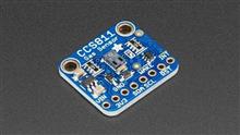
The CCS811 is an ultra-low-power digital gas sensor solution that combines a metal oxide (MOX) gas sensor with a microcontroller unit (MCU) that includes an Analog-to-Digital converter (ADC) and an I2C interface to detect a wide range of Volatile Organic Compounds (VOCs) for indoor air quality monitoring.
Basic Electronics Technology/TutorialsAccess:1359
Cecelia · March 24,2022
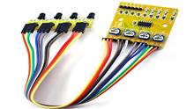
Infrared sensors are sensors that use the physical properties of infrared rays to measure. Infrared sensors are commonly used in non-contact temperature measurement, gas composition analysis, and non-destructive testing, and are widely used in medicine, military, space technology, and environmental engineering. Infrared sensors are sensors that use the physical properties of infrared rays to measure.
Basic Electronics Technology/TutorialsAccess:7878
 Anita · March 09,2022
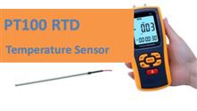
PT100 RTD Sensor is the most common type of platinum resistance thermometer. It is general use and is suitable for measuring high range temperatures as well as measuring duct temperatures. Due to its rugged construction, it can be used in harsh situations.
Basic Electronics Technology/TutorialsAccess:5932
Popular Posts
Hot Labels
Popular Parts