


KD-KA01
Cecelia is an accomplished electrical engineer with expertise in automation and control systems. She is a natural problem-solver and thrives on developing solutions that optimize performance and efficiency.
Transformers are electrostatic electrical devices with no moving parts that convert electrical energy from one voltage and current setting to another. The frequency of the current remains constant.
Transformers are classified by their function, i.e. step-up or step-down. A step-up transformer increases the voltage of the input current, while a step-down transformer reduces the voltage of the input current. The input voltage is called the primary voltage and the output flow is called the secondary voltage.
Typically, a step-up transformer is located at the power plant and steps up the voltage flowing from the power plant to the long-distance distribution grid. On the other hand, a step-down transformer reduces the voltage of the power flow received at the local distribution level. First, reduce long-distance traffic to a level acceptable to the local distribution, then reduce long-distance traffic again at each consumer node (residential and office).
Transformers work on the principle of mutual inductance. A changing magnetic field in one wire loop induces an electromotive force (EMF) in an adjacent wire loop, which is inductively coupled to the first coil. In the most basic terms, a transformer consists of two coils with high mutual inductance. The coils are electrically separate and they share a common magnetic circuit.
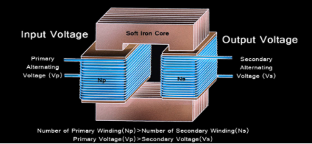
Figure: A step-down transformer has more primary windings than secondary windings
For a step-down transformer, the second coil has fewer windings than the first, allowing the voltage in the output current to be reduced.
The primary winding is the first set of coils and it is connected to an AC voltage source or primary voltage inflow. The secondary coil is connected to the load or the secondary voltage flows out, distributing the power out of the transformer.
The alternating current flowing in at the primary voltage generates an alternating magnetic flux. This induces a similar current in the secondary coil, creating a secondary voltage. Here, the reduction in the number of windings in the secondary coil effectively reduces the resultant voltage, thus "stepping down" the voltage to a lower value while maintaining a constant frequency.
Note that as the voltage decreases, the current increases, and the frequency remains constant. Therefore, the secondary coil in a step-down transformer usually has a larger gauge wire than the secondary coil. Since the primary voltage is low current, the wiring of the primary coil does not need too thick a wire. Conversely, the current flowing through the secondary coil increases, and the thickness of the wire must be increased. If the wires in the secondary coil are too thin, the wires can melt due to the buildup of resistive heat, resulting in catastrophic failure.
The step-down transformer is a transformer that converts the higher voltage at the input end into a relatively low ideal voltage at the output, so as to achieve the purpose of step-down. The step-down transformer is a very important piece of equipment in the power transmission and transformation system. Its normal operation is not only related to its own safety and the reliable power supply of users but also directly affects the stability of the power system. The configuration of the step-down transformer protection should meet the requirements that under any circumstances, the transformer cannot be burned, which will expand the accident and affect the stability of the power system.
The working principle of a step-down transformer is the principle of electromagnetic induction. Now, a single-phase two-winding transformer is used as an example to illustrate its basic working principle: when a voltage is applied to the primary side winding, the current flowing in the iron core generates alternating magnetic fluxes, which is commonly known as the main magnetic flux. The main magnetic flux will pass through the primary and secondary windings, and an induced electromotive force will be generated in the windings. At this time, if the secondary side is connected to the load, the current will flow out to generate electricity. Under its action, the windings on both sides induce potentials é1, é2 respectively, and the formula for the induced potential is: E=4.44fNm
In the formula:
E--the effective value of induced potential,
f—frequency,
N--the number of turns
The maximum value of the main magnetic flux is due to the difference in the number of turns of the secondary winding and the primary winding, and the magnitudes of the induced potentials E1 and E2 are also different. When the internal impedance voltage drop is omitted, the voltage magnitude is also different.
When the secondary side of the transformer is no-load, the primary side only flows through the current of the main magnetic flux, which is called the excitation current. When the secondary side is loaded and the load current flows, a magnetic flux is also generated in the iron core, trying to change the main magnetic flux, but when the primary voltage remains unchanged, the main magnetic flux is unchanged, and the primary side will flow through two parts of the current, part of the excitation current is used for balance, so this part of the current changes with the change. When the current is multiplied by the number of turns, this is the magnetic potential.
The transformer can convert the AC power of one voltage into another voltage of the same frequency. The main components of the voltage transformer are an iron core and two windings set on the iron core. The coil connected to the power supply receives AC energy, called the primary winding The coil connected to the load sends out AC energy, called the secondary winding Voltage phasor of the secondary winding of the primary winding U1 Voltage phasor U2 Current phasor I1 Current phase Quantity I2 electromotive force phasor E1 electromotive force phasor E2 number of turns N1 number of turns N2 is linked once at the same time, the phasor of the magnetic flux of the secondary winding is φm, and the magnetic flux is called the main magnetic flux.
A transformer is a common electrical device that can be used to convert an alternating voltage of a certain value into an alternating voltage of another value of the same frequency. A step-up transformer is a transformer used to convert a low-value alternating voltage into another higher-value alternating voltage of the same frequency, while a step-down transformer converts the higher voltage at the input of the power supply to a lower ideal voltage for the load. The principle of the transformer is to transfer the capacity through electromagnetic conversion and play the role of electrical isolation, as shown in the figure below.

I1 (I2), U1 (U2), and W1 (W2) are the current, voltage and coil turns of the primary (secondary) winding, respectively, and their quantitative relationship is U1/U2=W1/W2=I2/I1. Φ is the magnetic field line generated by electromagnetic induction, the physical entity where it is located in the iron core, and it is the magnetic circuit of the transformer.
In the step-down transformer, the primary winding is high voltage and the current is small, but because Φ needs to be generated by electromagnetic induction, the loss must be considered, so the voltage of the primary winding should reserve 5% of the loss, such as 10KV voltage, which is actually 10.5 KV; The secondary winding is low voltage and the current is relatively large. The winding itself and the voltage drop reaching the load end (electrical equipment) need to be considered. Therefore, the voltage of the secondary winding should also be reserved at about a 5% margin. The 380V voltage is actually 400V on the low voltage side of the transformer.
Then, if the step-down transformer is used as a step-up transformer, the low-voltage side needs to generate electromagnetic induction, and the high-voltage side is used as the load power supply, both of which need to consider the corresponding losses. If both are reserved 5%, it can just be achieved, and the output voltage of the inverter has a large adjustable range, which can meet the requirements.
That is to say, in theory, the step-down transformer can be used as a step-up transformer.
However, in the practical operation process, the step-down transformer is different from the step-up transformer in structure and protection. If the step-down transformer is used as a step-up transformer for a long time, its stability and life will be affected. Moreover, n the current policies and normative documents, it is generally required that the self-generated and self-consumption surplus power grid projects should be larger than 50% of the generated power, and the connection capacity should not be larger than 25% of the upper-level transformer.
The abnormal situation of the transformer is inevitable. If we can find it in time and take reasonable countermeasures, the occurrence of accidents can be greatly reduced. The common abnormal phenomena of transformers mainly include:
Increased buzzing or abnormal pitch;
A significant or rapid rise in temperature;
The oil level of the transformer or bushing is lower or higher than the allowable value, the oil color changes, and the test fails;
Cracks, discharge marks, or discharge sounds appear in the casing;
Overheating of casing screws or terminal blocks;
Light gas protection action.
The following is an introduction to the causes and solutions of several common abnormal situations:
1. When the temperature of the transformer rises abnormally
Check the load condition of the transformer and whether the three-phase load is balanced. When overload occurs, reduce the output and limit the load.
Check whether the radiator is related to the temperature of the wood body: whether the cooler is operating normally; whether the ventilation device of the unit cooler is normal; if the fan motor is out of operation, check whether the various power fuses corresponding to the out of operation fan are blown, whether the thermal relay is activated, whether the switch contact is good, whether the secondary circuit is disconnected, etc.
2. Check the thermometers of the transformer
Check whether there is oil leakage or other reasons that cause the oil level to be too low to cause the temperature to rise; after checking that the cooling device and the temperature measuring device are in good condition, and the oil temperature still rises after reducing the load, the transformer should be stopped immediately.
3. The oil level drops
If the oil level drops slowly, check whether the oil leaks or the oil level drops due to low temperature; if the oil level drops rapidly, deactivate the gas protection, immediately try to prevent the oil leakage, and notify the maintenance personnel to deal with or inject oil.
4. Light gas protection action processing
Those with backup transformers should be put in; those without backup transformers should pay close attention to the operation of the transformers, and it is strictly forbidden to withdraw from heavy gas protection at this time.
Take gas and oil samples in the gas for analysis; check whether there is gas in the transformer gas relay to determine whether the protection is in action. The protection pressure plate should be put into the signal before inspection and put into the trip after sampling. If there is an internal fault, the transformer must be stopped, if it is air, the gas relay vent valve should be opened to release the air. If the gas protection wooden body is faulty, abnormal or the insulation of the secondary circuit is poor, the trip-out II relay should be disconnected.
5. Transformer overload operation
Before overload operation, check whether the transformer has serious defects (such as abnormal cooling system, serious oil leakage, local overheating, abnormal analysis results of dissolved gas in oil, etc.), or the insulation is weak, and under this situation, the transformer cannot operate under the situation of overload.
When the transformer is overloaded, the standby cooler should be put into operation immediately, and the temperature of the upper layer of the transformer, the ambient temperature, and the time should be observed. And record overload time and overload multiples, overload multiples during normal overload operation.
The power plant generates 20 kV of electricity, which is then boosted to 440 kV for distribution over long distances. When received at the local substation, the voltage is reduced to 11 kV using a step-down transformer. From here, for distribution to individual consumers, another step-down transformer reduces the voltage to the standard 220V suitable for consumer use.
In most areas, the household voltage is 220V. However, in the U.S. and neighboring countries, household sockets operate at 110 or 120V. Connecting 220 V equipment to a 110 V power outlet may damage the equipment. Fortunately, inexpensive adapters (Figure 1) are easy to use and can completely solve this problem. They can be found for less than $20 at most electronics stores. Many of these European-made devices clearly state that they can be used in the United States.
This is a typical step-up transformer adapter working from 110V to 220V
Transformers are an expensive but essential aspect of the power supply chain. Purchasing transformers requires significant capital expenditure, and they are expected to last throughout their projected service life. In practice, however, these transformers typically fail around half their life expectancy. Windings, tap-changers, and bushings in service are often the main cause.
However, inadequate maintenance planning is not the only responsibility. Transformers are often not matched to the expected conditions of use, causing unnecessary stress to the equipment after use. Even if the transformer is completely stationary, with no moving parts, the intensity of the current flowing through the coil will cause the coil itself to wear out. The same goes for tap-changers and bushings. Over time, the integrity of these materials can be compromised, either mildly or catastrophically.
To prevent such premature failures, transformers must be specified carefully. After installation, commissioning should also be done with great care. Operating conditions must be strictly controlled and maintenance plans must be carried out regularly and thoroughly. With these provisions, the transformer is likely to provide optimum performance throughout its predicted life.
Core
Additionally, care should be taken when selecting the material grade for the transformer core. While higher grade materials are generally more expensive, they usually result in a longer life expectancy. Match material grades to normal service conditions and the expected service life of the transformer.
Winding
Carefully choose the type of metal used in the transformer windings. The purpose here is to minimize resistance in the wire while maximizing conductivity. In this case, copper is usually the best choice, although copper is usually more expensive than aluminum, which is a substitute.
Copper is often the most cost-effective choice in the long run because it has less resistance to current flow than alternative materials. This reduced resistance results in less power loss, improving the long-term efficiency of the device. Another benefit is the reduction of heat build-up in the system, as the resistors generate heat when using alternative materials. It is important to understand the physical arrangement of the coils.
Insulation
Insulation is critical to the proper operation of the transformer and to the safety of personnel in the field. Match it to the expected operating conditions to ensure the best choice of insulation material and configuration.
Transformers are critical to the efficient operation of the national grid. These devices allow the conversion of electrical energy into the correct voltage-to-current ratio for long-distance transmission and local distribution. Due to their cost, transformers should be chosen carefully. Proper operation and proper maintenance can extend the life expectancy of a transformer installation.
Related:
Step-Up Transformer: All You Need to Know
Power Transformer: A Basic Electronics Tutorial

Cecelia is an accomplished electrical engineer with expertise in automation and control systems. She is a natural problem-solver and thrives on developing solutions that optimize performance and efficiency.

Cecelia · April 21,2022
A step-up transformer is a type of transformer, which has the function of voltage compensation and boosting, and it is also called a step-up compensator.
Basic Electronics Technology/TutorialsAccess:5730

Cecelia · April 20,2022
A power transformer is a static electrical device that is used to convert a certain value of AC voltage (current) into another or several different values of voltage (current) with the same frequency.
Basic Electronics Technology/TutorialsAccess:3528

Cecelia · April 01,2022
The isolation transformer refers to the transformer with electrical isolation between the input winding and the output winding. The isolation transformer is used to avoid accidental contact with the live body at the same time. The isolation of the transformer is to isolate the respective currents of the primary and secondary windings.
Basic Electronics Technology/TutorialsAccess:5920

Cecelia · March 31,2022
Audio transformers are low-frequency transformers and are mainly used for constant-voltage power amplifiers for long-distance broadcast transmissions that do not require high sound quality.
Basic Electronics Technology/TutorialsAccess:5617
Popular Posts
Hot Labels
Popular Parts