Multiplexing involves communication of various digital data streams over a common communication channel. Basically, a multiplexer enables effective transmission of several signals via a single channel. Multiplexers have various applications in the electronics sector including selection of data, routing signals, among others. In this tutorial, we provide a comprehensive overview on the concept of multiplexers, what they are, their various types along with their circuit designs, and their applications.
What are multiplexers?
Multiplexers, also commonly known as MUX represent a multi-input –single-output switch. This means there are several input lines and only one output line. A multiplexer also has a line selector (select switch) which determines which of the input lines gets connected to the output. It basically selects lines from an address bus that chooses the specific input line to send to the output. Figure 1 represents various components of a multiplexer.
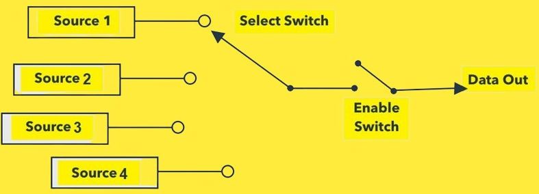
Figure 1: Components of a MUX
Working mechanism of a multiplexer
A multiplexer has ‘n’ input lines, ‘m’ select lines and 1 output line. The select lines choose which input line gets connected to the output. When the number of selection line is m, then the possible number of input lines in designated as 2m. The following equation applies:
ð n (input lines) = 2m
This means, for a multiplexer with 2 select lines, then the input lines are 4 and when it has 3 select lines, then the input lines are 8.
For example, consider a 4:1 mux shown in figure 2 with inputs D0, D1, D2 and D3. It has 2 select lines S0 and S1. The select lines determine the mux operation as per the truth table below:
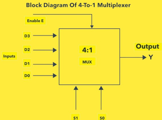
Figure 2: 4:1 MUX
Truth Table |
S1S0 | Output |
00 | D0 |
01 | D1 |
10 | D2 |
11 | D3 |
To explain the above truth table; when S0S1 is 00, input D0 gets connected to the output. When S0S1 is 01, input D1 is connected to output and so on. The mux acts as a controllable switch, connecting one of the many inputs to its sole output based on the select line bits.
Types of multiplexers
For the purpose this tutorial, we will evaluate the common types of multiplexers frequently used in Integrated circuits (ICs).
2:1 multiplexer
The configuration of a 2:1 multiplexer is illustrated in figure 3. It comprises of 1 select line (S), 2 input lines (D1 and D0) and 1 output (Y). Considering there are two inputs, the select line can choose either of the inputs. i.e. D1 and Do inputs are selected when select line is high and low respectively.
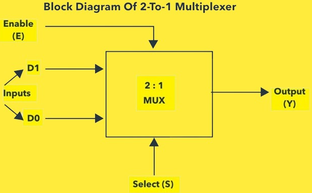
Figure 3: 2:1 multiplexer
Based on the above truth table, when S=1, the output is D1 and when S=0, then the output is D0. The corresponding Boolean equation of a 2:1 multiplexer can be generated as shown in equation 1.
Y = SD1 +SD0………………………………. (Equation 1)
In this multiplexer, the logic circuit comprises of 1 NOT gate, 1OR gate and 2 AND gates as shown in figure 5. Accordingly, when s=1, the AND gate output on the upper side is 0 while the AND gate output on the lower side is D1. Hence, the OR gate output is D1. Correspondingly, when s=0, the AND gate output on the upper side is 0 while the AND gate output on the lower side is D0. Hence, the OR gate output is D0. Examples of 2:1 multiplexer in real world applications includes IC 74158 and IC 74157.
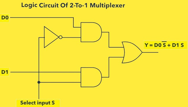
Figure 4: logic circuit of a 2:1 multiplexer
8:1 multiplexer
The 8:1 multiplexer shown in figure 6 comprises 8 input designated as D0 –D7; one output (Y) and 3 select lines designated as S0, S1 and S2. Inputs are selected based on the combinations of the select lines.
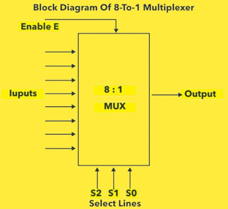
Figure 5: 8:1 multiplexer
Truth Table |
S0S1S2 | Output |
000 | D0 |
001 | D1 |
010 | D2 |
011 | D3 |
100 | D4 |
101 | D5 |
110 | D6 |
111 | D7 |
Based on the truth table presented above, the corresponding Boolean equation can be written as illustrated in equation 2.
Y = S0S1S2D0 + S0S1S2D1 + S0S1S2D2 + S0S1S2D3 + S0S1S2D4 + S0S1S2D5 + S0S1S2D6 + S0S1S2D7…. Equation 2
Considering the Boolean equation, the 8:1 multiplexer logic circuit contains seven NOT gates, eight AND gates and one OR gate as illustrated in figure 8. Notably, this multiplexer has an ‘ENABLE’ pin whereby when set to 0, the select lines makes the required combination to produce an output but when set to 1 the multiplexer is turned off.

Figure 6: Logic circuit of an 8:1 multiplexer
There are other several common types and configurations of multiplexers including:
Analog Mux: Used for analog signals, have low on-resistance and high off-isolation.
Digital Mux: Used for standard logic signals. Available in CMOS, TTL, ECL, etc.
Demultiplexer: A multiplexer in reverse, it switches a single input over several output lines.
Bidirectional Transmission Gate Mux: Passive switches that can be used for bidirectional signals.
Multistage Multiplexers: Larger multiplexers can be constructed by using smaller muxes in succession.
High Frequency Muxes: Specialized muxes to work at high frequencies > 1 GHz.
Multiplexer applications
Communication
Multiplexers are employed in routing data over various shared channels such as in telephony. During routing, data from various sources are routed to a single destination. One such application is display of several multidigital counters (BCD) each at a given time. The most commonly used multiplexer in this application is the IC 74157.
Generation of logic functions
Multiplexer have the capability of developing logical expressions through the use of logic gates. As such the multiplexer is often connected to in a way that allows it to duplicate various truth table logics. This is important in applications as it minimizes the quantity of logic gates or IC required to carry out logic manipulations. One such application is make use of IC 74151A.
Other applications include disk storage where multiplexers help in routing data from/to multiple disks and heads via shared busses. In medical imaging, multiplexers find applications in analog signal routing for CT scans and MRI.
Major benefits that make multiplexers
ð Reduced wiring - Multiplexers allow many signals to share one wire path, reducing wiring clutter.
ð Channel selection - Any input can be selected at any time under the control of selector lines.
ð Bandwidth optimization - Time division multiplexing through a mux optimizes bandwidth utilization.
ð Logic function implementation - Multiplexers can realize any logic function by acting as programmable logic.
Conclusion
To sum up, multiplexers offers a variety of functionalities allowing switching multiple signals or data streams through a common channel. This tutorial has covered essential aspects of multiplexers from configurations to applications which are key to design of digital logic circuits in various electronic systems.
 Candice ·


